There is a sump in ground floor where water is stored and an over head tank from where water is supplied to the entire building. A motor is used to pump the water from sump to overhead tank whenever water in the tank is 'empty'. The motor is switched OFF once the overhead tank is 'full'. If the sump is 'empty' motor should not be turned ON as it causes 'dry run' of the motor. Manually monitoring the above conditions to operate the motor could be painstaking. Hence an automatic controller system is built to switch the motor ON and OFF as per the conditions above. The controller also provides a 'manual' mode to operate the motor manually.
A simple, single chip (555 timer) circuit can automate the operation. Such a 'controller system' will need following:

A simple, single chip (555 timer) circuit can automate the operation. Such a 'controller system' will need following:
- Sensors which can detect the water levels in tank and sump.
- An electronic circuit (herein referred to as controller) which turns the motor ON and OFF based on the sensor information.
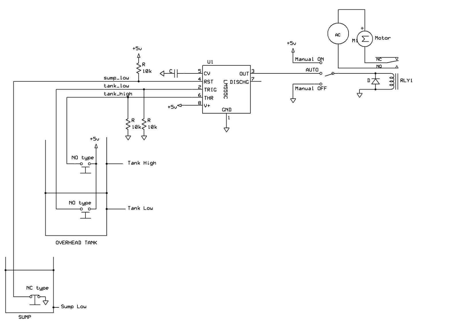
Two types of sensors are used for this system:
- NO(Normally Open) sensor - opens the circuit when water is below the sensor level and closes the circuit when water is above the sensor level.
- NC (Normally Closed) sensor - closes the circuit when water is below the sensor level and opens the circuit when water is above the sensor level.
Two types of sensors are used to avoid a NOT logic that will be otherwise required in the circuit. The details of the sensors are provided at the end of this blog.
Controller requires following 3 sensors to be installed:
- tank_low: This is a ‘NO’ type sensor installed at a lower height in the tank to detect the 'empty' level of the tank. This sensor is connected to Pin 2 of 555 timer. When water in overhead tank falls below this sensor, the sensor circuit is 'open' and motor is turned ON. (Refer to controller circuit diagram).
- tank_high: This is also a ‘NO’ type sensor installed at an higher level in the tank to detect the 'full' condition. This sensor is connected to Pin 6 of 555 timer. When water in overhead tank reaches above this sensor, the sensor circuit is 'closed' and motor is turned OFF.
- sump_low: This is a ‘NC’ type sensor installed at a lower height in the sump to detect the 'dry run' condition. This sensor is connected to Pin 4 of 555 timer. When water in the sump falls below this sensor, the sensor circuit is 'closed' and motor is turned OFF. Since this sensor is connected to the Reset pin (Pin-4) of 555 timer, the motor is turned OFF when water is below this sensor irrespective of the water level in the tank. Only when water is above this sensor, 555 timer is out of reset and hence will respond to the information from tank sensors.
Advantages of this controller system:
- Single chip (555 timer and some resistors are required) solution and hence low maintenance.
- Inexpensive as both the sensors and the controller circuit is built with inexpensive parts.
- The circuit can be powered by the AC mains (using a 5V DC adaptor). When AC power is off, circuit is also switched off and no current is drawn to un-necessarily latch the electro mechanical relay
- The operation of sensors is independent of conductivity of the liquid (here water). Hence this system can be used for any liquid level controller systems
Sensor mechanim:
Sensor is made up of a wooden base, which can float on water and two sensor leads that are connected to controller circuit. A metal strip is attached to wooden base as shown in pictures below. In 'NO' type sensors, when water is below the sensor level, wooden base floats below the sensor leads and hence the sensor circuit is open. When water level reaches or crosses sensor level, wooden base floats and touches the sensor leads closing the sensor circuit. In 'NC' type sensor, wooden base is mounted above the sensor leads as shown in the pictures below and hence the operation is reversed with respect to 'NO' type.


No comments:
Post a Comment